

Tutorial - Building Your Module Air Sensor
Version 1 (2023)
Module Air is an open-source connected device for measuring and displaying
indoor air quality, created and developed by AtmoSud as part of the Sensorthèque
project funded by the South region.
The objective is to present air quality data in the most
intuitive way possible.
The Module Air is equipped with two probes for indoor air measurement:
- Carbon dioxide (CO2): allows evaluation of confinement levels and evolution under occupation conditions
- Fine particles (PM10, PM2.5 and PM1): evaluate the evolution of indoor fine particle concentrations over time
- Volatile organic compounds
Required Materials
Check that you have all the necessary components and tools:
- Matrix Led Panel P3 Screen, 64x32 LED, 192x96mm
- NextPM Fine Particles Probe
- CO2 MH-Z16 Probe
- BME280 Temperature and Humidity Probe
- CCS811 VOC Probe
- ModuleAir PCB Board (ESP32 with connections)
- 2m Power Cable (USB Type A - stripped)
- USB Charger 5v 3a
- 16-pin Cable (8x8)
- 5 MDF (medium density fiberboard) panels for the housing
- 2 plexiglass panels
- 4 brass F/F 40mm spacers
- 4 m3 18mm screws and 8 m3 8mm screws
- 1.5mm precision flat screwdriver
- 2mm allen key
- Wood glue
- Spray paint (optional)

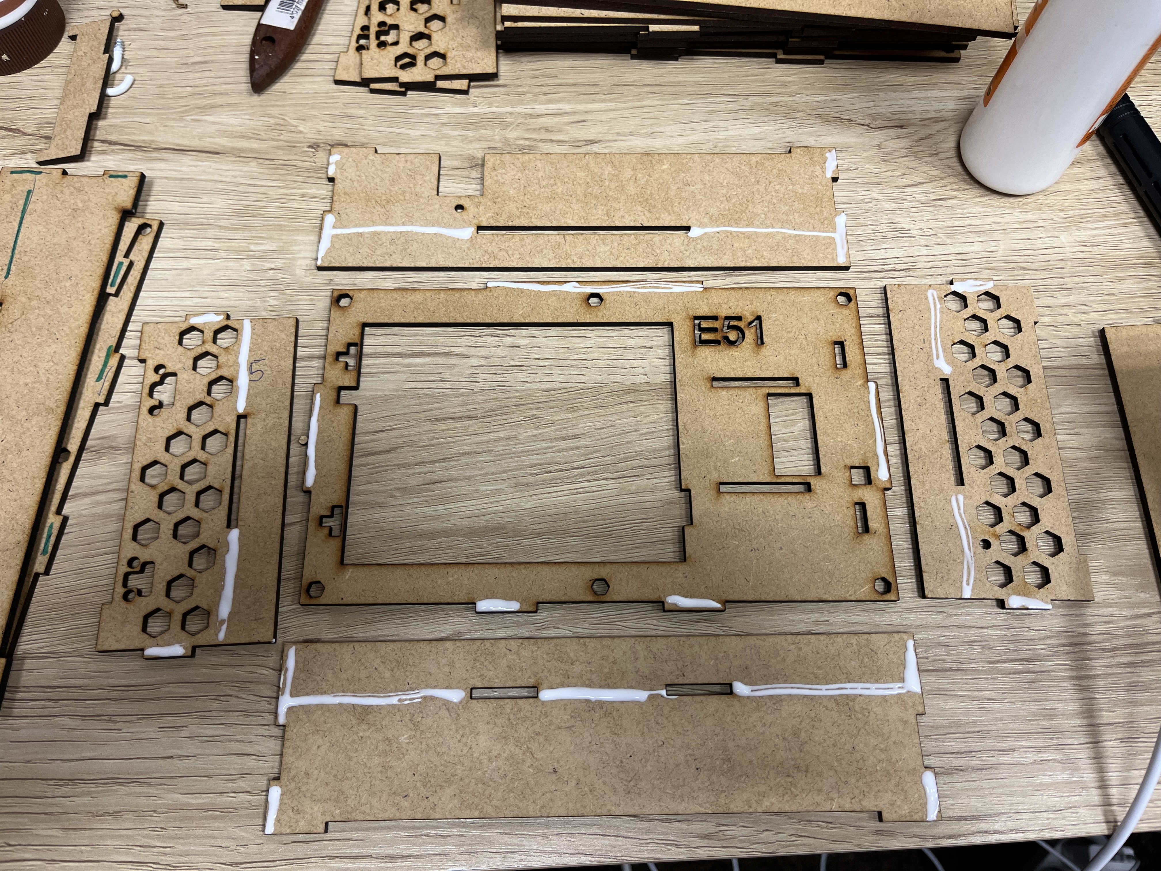


Step 1 - Gluing
The first step consists of assembling the wood elements (MDF) with wood glue. Apply glue as shown in the photos above then assemble the elements. Make sure they are well aligned and perpendicular. Let dry for 10 to 15 minutes.


Step 2 - Screen Installation
Place the LED screen as shown in the photos above. Make sure the arrows are pointing in the right direction (from bottom to top and from left to right). Use a screw to fix the screen.


Step 3 - Adding the Printed Circuit Board
The printed circuit board connects to the screen via the connector located underneath. Be careful to respect the alignment with the holes so you can fix a screw (see photos). Then connect the white connector with the red and black cables to the center of the screen. Finally, use the 16-pin cable to connect the screen and the PCB.


Step 4 - USB Power Cable Installation
Pass the power cable through the small hole provided in the housing. Insert the red cable and the black cable into the green connector. Be careful to respect the polarity as shown in the photo above:
- red cable: 5v side
- black cable: GND side
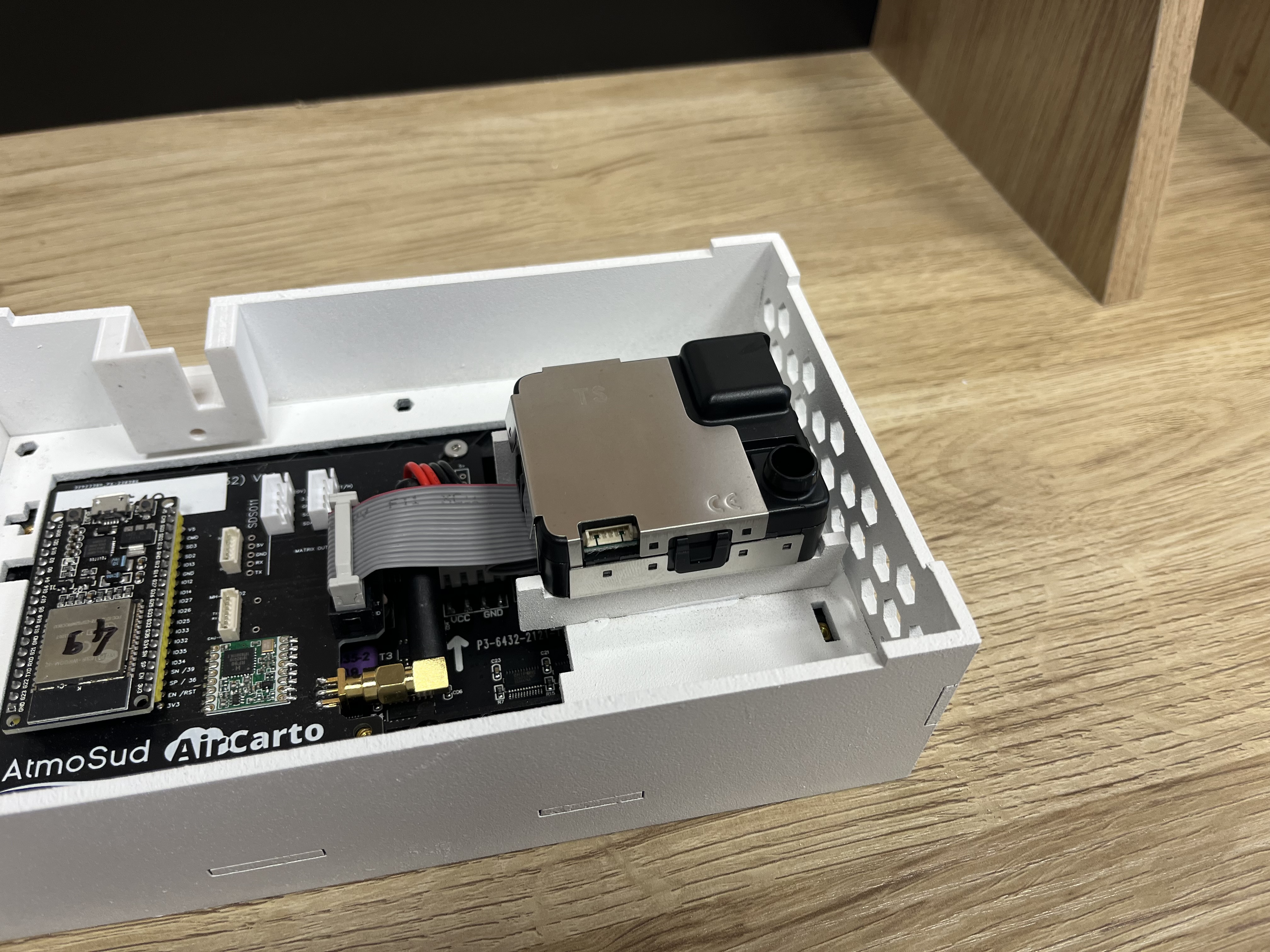
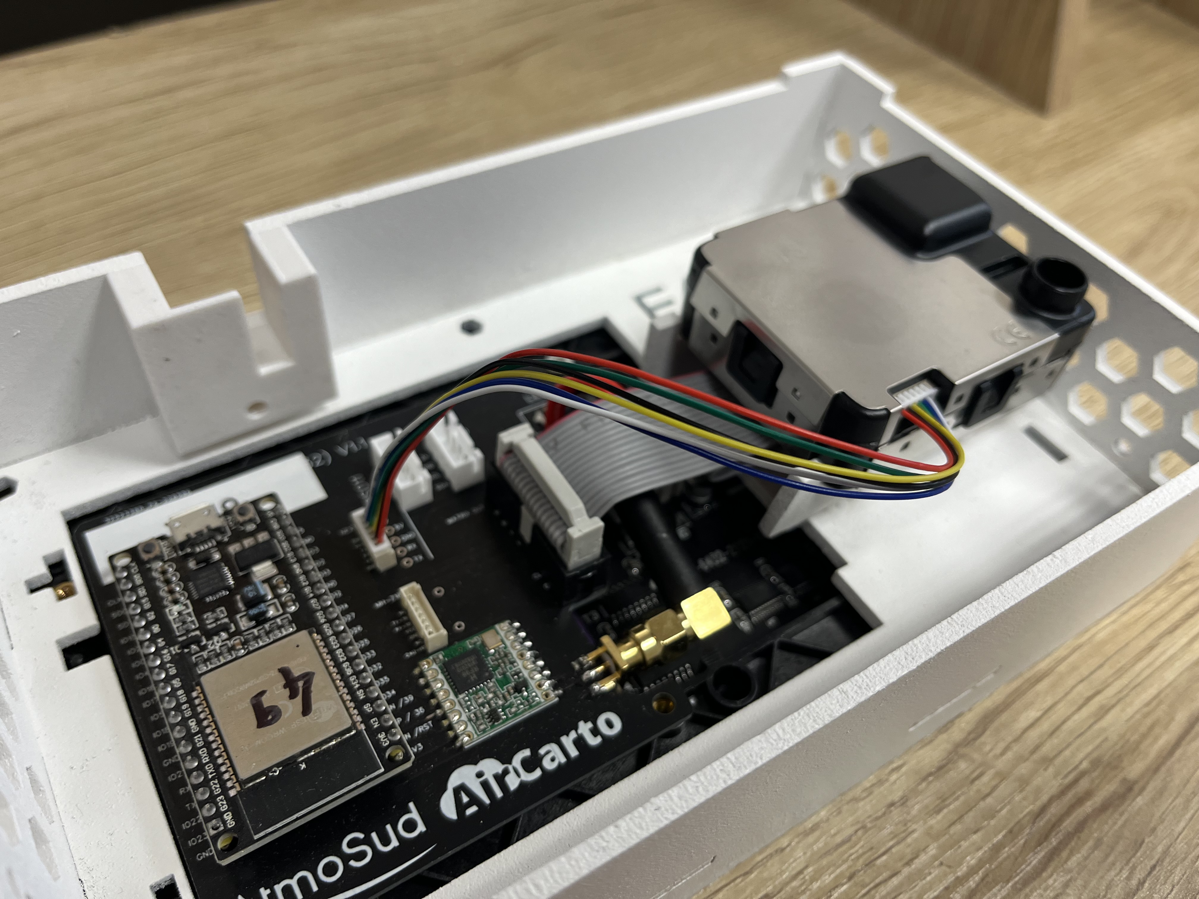
Step 5 - Fine Particles Probe Installation
The fine particles probe (NextPM) is fixed inside the housing by resting on the two supports. Then connect the probe with the printed circuit board using the multi-colored cable.


Step 6 - CO2 Probe Installation
The CO2 probe is fixed on top of the housing. Use the small plastic piece as a support and make the connections as shown in the photos above.


Step 7 - VOC Probe Installation
The VOC probe must be fixed on the left side of the housing. Use two screws and two nuts to fix the probe as shown in the photos.


Step 8 - Temperature and Humidity Probe Installation
The temperature and humidity probe is placed next to the VOC probe. Then connect both cables to the printed circuit board (PCB).


Step 9 - Finalization
To complete the housing assembly, install the paper sheet under the transparent plexiglass plate and place the screws as well as the brass spacers as shown in the images above. Then install the plate in front of the screen. Finally, use the second plexiglass plate to close the housing. Place the screws on the spacers to finalize the housing assembly.
Connect your sensor to WiFi network
When plugged in, the Module Air sensor will create a WiFi network named
"moduleair-xxxxx" (ex: moduleair-A546GF) you can connect to it with a computer
or smartphone using the password "moduleaircfg".
Please note, the Module Air WiFi network will only be active for a few minutes after
startup. If the network is not detected by your devices, please turn the Module Air
off and on again.
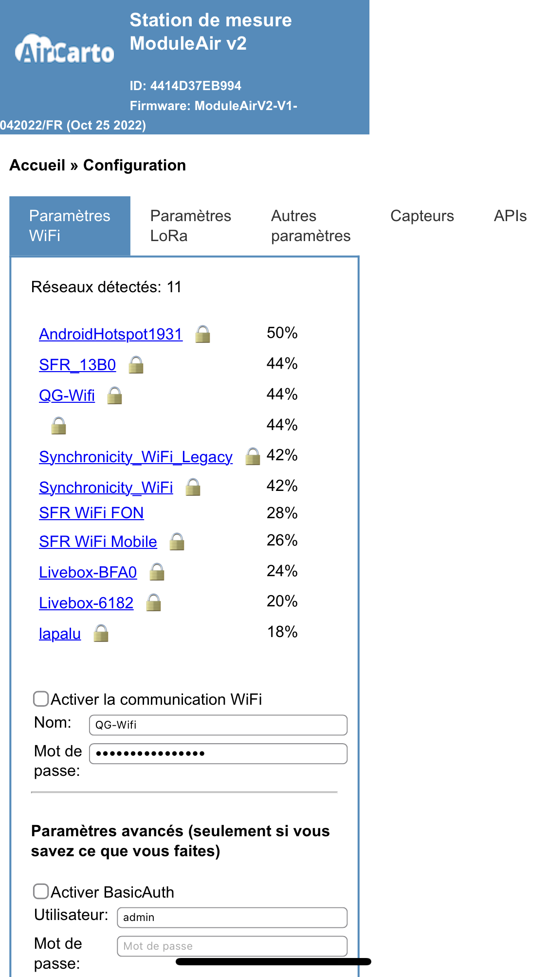
Once connected, the configuration web page should open automatically (see
opposite).
If it doesn't, open a browser and go to http://192.168.4.1/
The configuration page shows the WiFi networks that the Module Air can
connect to. Click on your home network, enter the password and click
the "Save and restart" button.
The Module Air will then restart and attempt to connect to your network.
If the connection is successful, the "moduleair-xxxx" WiFi network disappears.
If the connection fails (wrong password or signal too weak), the "moduleair-xxxx" WiFi
network will still be available. In this case you need to retry the connection.
Technical note: it is possible to modify other parameters on the
configuration page but this requires good computer knowledge (more
detailed information is available on the Module Air project github.)
Once your Module Air is connected to the WiFi network you can consult the
measurement data by going to the my Module Air page.
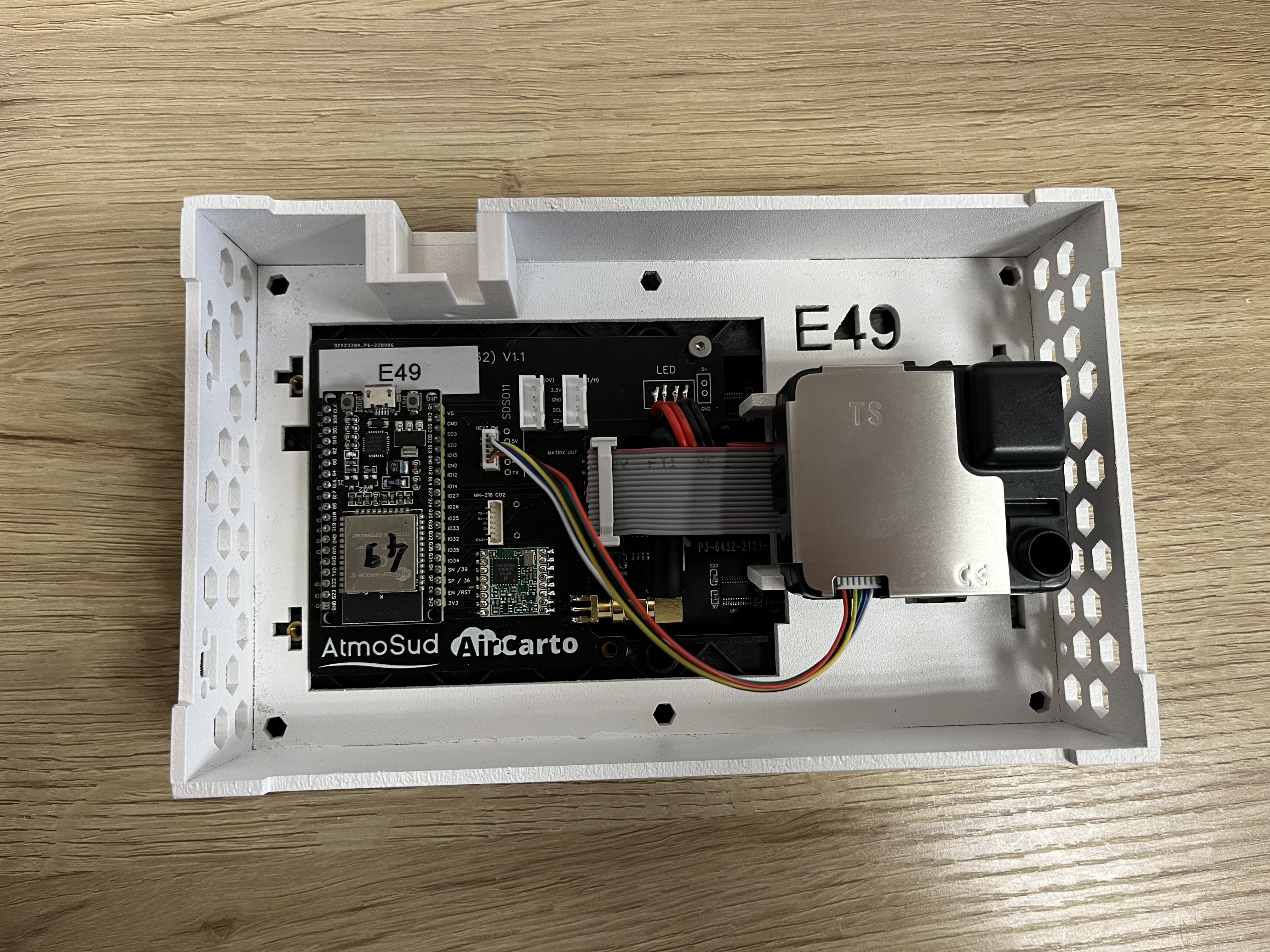
The sensor name is written inside the housing and the identification
number (id) is engraved on the plexiglass.